Structural Testing System
Instrument Details

| Make | : | Bridge Diagnostics, Inc. (BDI-STS) |
| Model | : | Structural Testing System |
| Specification | : |
Channels: 4 to 128, Expandable in multiples of 4
Accuracy: ± 0.2% (2% for Strain Transducers)
Sample Rates: 0.01 to 1,000 Hz
Max. Input Voltage: ± 10V
Power: 85 - 264 VAC, 47-440 Hz
Excitation Voltages: 5VDC @ 200mA
A/D Resolution: 2.44mV bit (14-Bit ADC)
PC Interface: USB 1.1 Port (Compatible with USB 2.0)
The Structural Testing System II by Bridge Diagnostics, Inc. (BDI-STSII) has been designed expressly for performing live-load tests on highway and railroad bridges. Developed through the experience of field testing more than 200 structures, the BDI-STSII is very portable, lightweight, and efficient to implement. The BDI-STSII allows a typical short- to medium-span bridge or similar structure to be instrumented and load tested with up to 64 sensors in less than a day by a two-person crew.
The BDI-STSII was developed because most data acquisition systems are so application-general that they require an electrical engineer or computer specialist to configure them. Furthermore, other systems often require soldering and other tedious procedures in order to assemble them. The BDI-STSII eliminates these hassles and allows the structural engineer to concentrate on evaluating the structure.
Working Principles
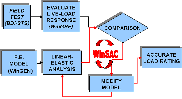
The BDI Suite of analysis and modelling software (WinSac, WinGen and WinGRF) was designed to make the integrated approach a routine process.

WinSAC (Structural Analysis and Correlation
Key Features:
- General purpose linear-elastic 3-D frame and finite element analysis program.
- Truck loading and truck path definition to simplify analysis of bridge systems.
- Computation of results at sensor locations (strain, rotation, displacement).
- Statistical comparison and error analysis of results with measured responses.
- Optimization process to calibrate model (minimize error between measured and computed responses).
- Generate response envelopes for series of load cases (truck path) and combine envelopes for multi-lane load conditions.
- Calculate Load Rating Factors and identify critical elements.
![]()
WinGEN (Model generation for planar bridge structures)
Key Features:
Modelling
- Simple parametric modelling of planar bridge structures.
- Import DXF files from AutoCAD or IntelliCAD for complex 3-D models.
- Visual implementation of all structural geometry, boundary conditions, cross-section definition and assignment, and loading.
Load Test Simulation
- Visual sensor placement on model. Strain gages, LVDTs, tilt meters can be applied to model at same locations as in field and identified with the same Intelliducer name to assure data comparisons are done accurately.
- Truck loading and truck path simulation.
- Association of load test data with modelled truck paths. STS data points that correspond to each analysis load case (truck position) are retrieved for data comparison.
WinGRF (Data viewing, processing and comparison)
Key Features:
Data management
- Load multiple STS data files.
- Store workspaces with STS data, WinSAC results, and graph settings.
- Edit STS load position markers.
- Associate load events with STS data files and series of WinSAC load cases.
Plotting
- Plot response histories as function of time, load position, or measured data.
- Calculate and plot common data functions (neutral axis, average, curvature, FFT)
- Plot measured responses with computed responses provided by WinSAC.
Data Processing
- Extract maximum and minimum values for each sensor and provide associated load position or event.
- Extract data for specified load position or event.
- Digital filter data to reduce noise or unwanted frequencies.
- Combine data files from multiple instrumentation setups with common loading.
- Average multiple data files with common load application.
- Perform and update stress cycle data (rainflow histograms) for fatigue analyses.
Applications
All types of bridges:
- Steel
- Pre-stressed concrete
- Reinforced concrete
- Timber
- FRP composite materials
- Slabs, T-beams
- Girder bridges
- Box beam bridges
- Trusses etc
User Instructions
- Access to the superstructure: If the terrain below the structure is suitable, usually two extension ladders can be used for access. Exceptions would be if the structure is too high in the air for ladders, or if it is a concrete slab (no girders for supporting the ladders). In this case, scaffolding, a bucket truck, scissors-lift, or snooper vehicle (UBIT) will be needed.
- Traffic control: This consists of one lane closure at a time for a two-lane bridge, and two lanes at a time (if possible) if the bridge carries three or more lanes of traffic.
- Loaded vehicle with known axle weights: In general, a three-axle tandem dump truck has been used to complete the load tests. The truck is first loaded up to its legal load (usually somewhere near 25 tons) and then weighed at the local scales or by a weight enforcement crew
- Generator and Miscellaneous: At least a 2 kilowatt, 110 AC generator is required for running the equipment and other power tools.
Contact Details
CSIR-Central Road Research Institute,
Delhi-Mathura Road, New Delhi-110025
Phone: +91-11-26848917 (Director), 26312412 (COA office), 26832173 (Reception)
Fax: +91-11-26845943
Email: director [dot] crri [at] nic [dot] in
Instrument Usage Charges(Including GST)
Inspection and Testing Charges: Rs./- per span of Bridge
The Demand Draft should be payable in favour of“The Director, CSIR-Central Road Research Institute, New Delhi”
Letter, DD & Samples send to “HOD-BES, CSIR-Central Road Research Institute, New Delhi


